AR-powered spatial inspection platform for large industrial parts. Built for wind turbine blade QC; expanding to construction and shipping.
Product overview
AR-anchored defect records.
Directly on the part.
Roboscope replaces paper logs and manual measurement with spatial AR markers anchored directly on physical surfaces. Built for wind turbine blade QC; expanding to construction and shipping.
- AR defect markers anchored on physical surfaces (~5 cm accuracy)
- Capture type, location, and dimensions in a single session
- Session auto-registration via work task router scan
- Direct ERP / QC system integration — no manual re-entry
- Built-in edge case escalation — replaces ad-hoc email chains
- ML vision models for defect types, structure, and paintwork
Industries
- Wind turbine blades
- Large aerospace structures
- Marine & shipbuilding
- Construction
- NDT on large surfaces
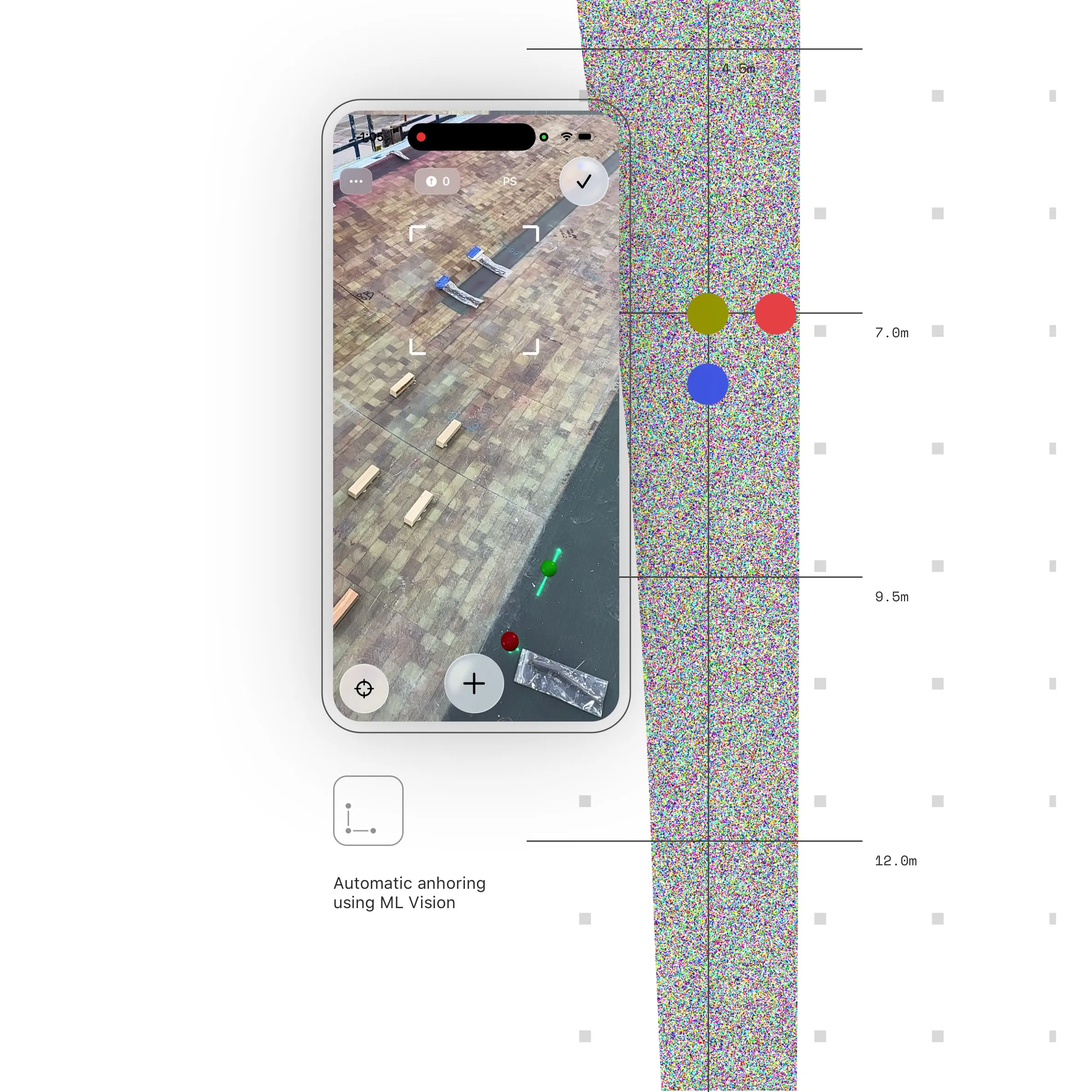
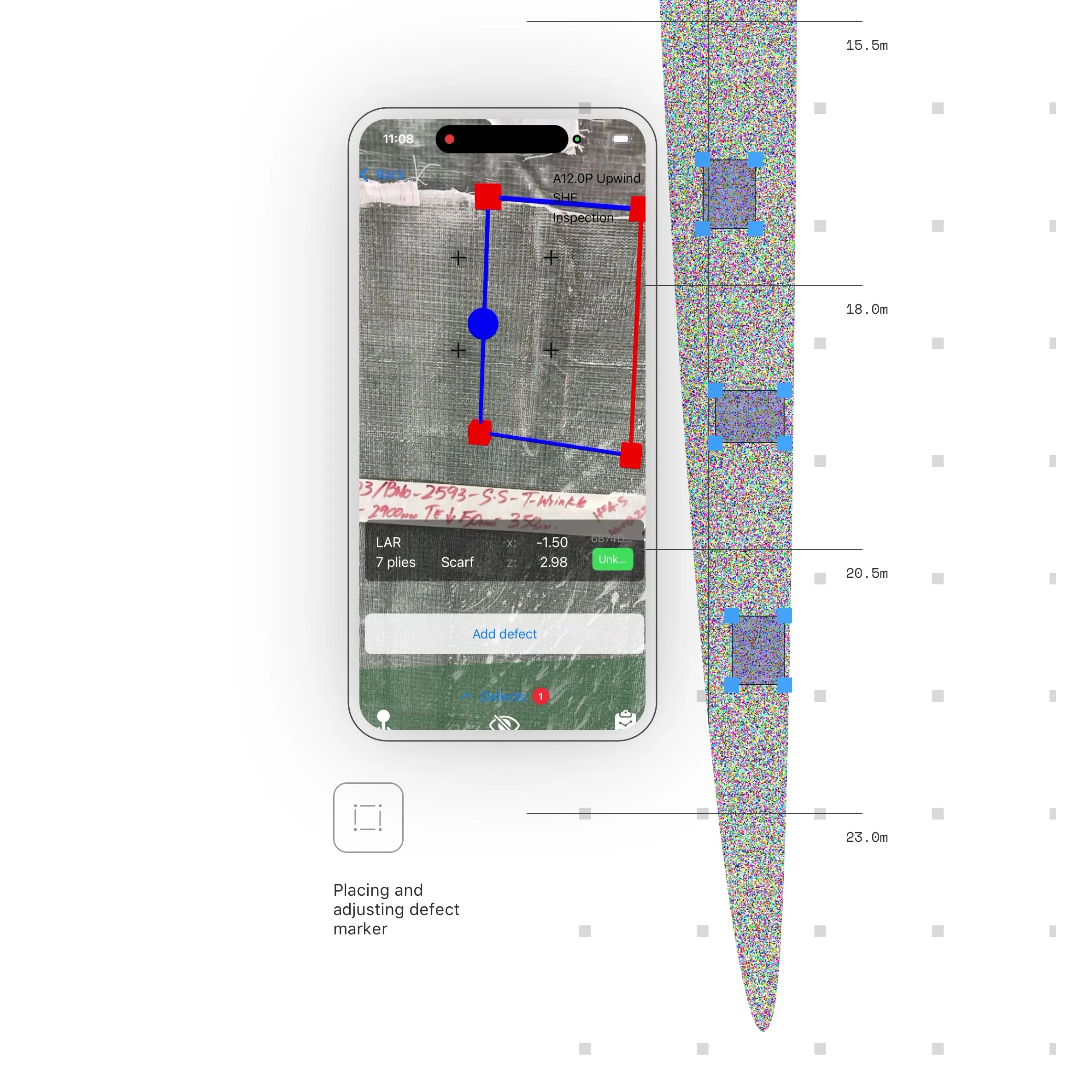
AR spatial marker system
Place defect markers directly on physical surfaces
Using iPhone AR, inspectors anchor digital defect markers at the exact physical location on the part. No manual measurement, no coordinate entry — position captured spatially in a single session.
-
~5 cm
AR placement accuracy on surfaces
-
Single session
Full defect registration without re-measurement
-
iOS native
Native iPhone application, optimised for handheld use
Captured per defect
- Defect type
- Spatial location (AR anchor)
- Dimensions
- Photographic evidence
- Inspector ID & timestamp
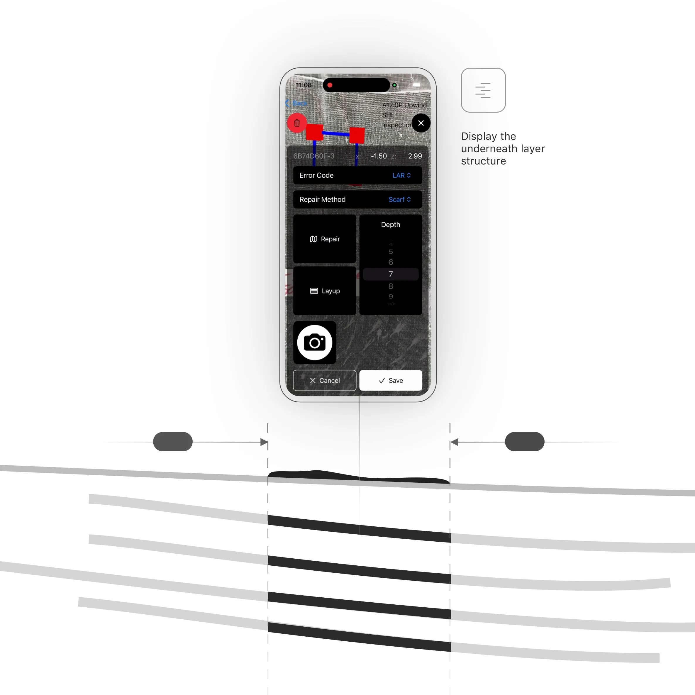
Layup Registration Table
Full layer breakdown at every defect location.
The Layup Registration Table maps every AR-anchored defect to the exact composite layers affected at that point on the part — giving engineers a precise cross-section view without disassembly.
- 1
Locate
AR anchor position is resolved against the part's layup geometry to identify the zone.
- 2
Layer lookup
LRT returns the ordered stack of plies at that coordinate — material, orientation, and thickness per layer.
- 3
Depth assessment
Defect depth is cross-referenced with the layer stack to determine which plies are affected.
- 4
Severity grading
Each affected layer is graded individually; structural plies trigger automatic escalation.
- 5
Export
Full layer-annotated defect record exported to ERP / repair workorder with ply-level detail.
LRT data per defect
-
Zone ID
Named layup zone resolved from AR anchor coordinates
-
Ply stack
Ordered list of plies with material, angle, and nominal thickness
-
Affected layers
Subset of plies intersecting the defect depth envelope
-
Repair class
Repair category derived from affected structural ply count
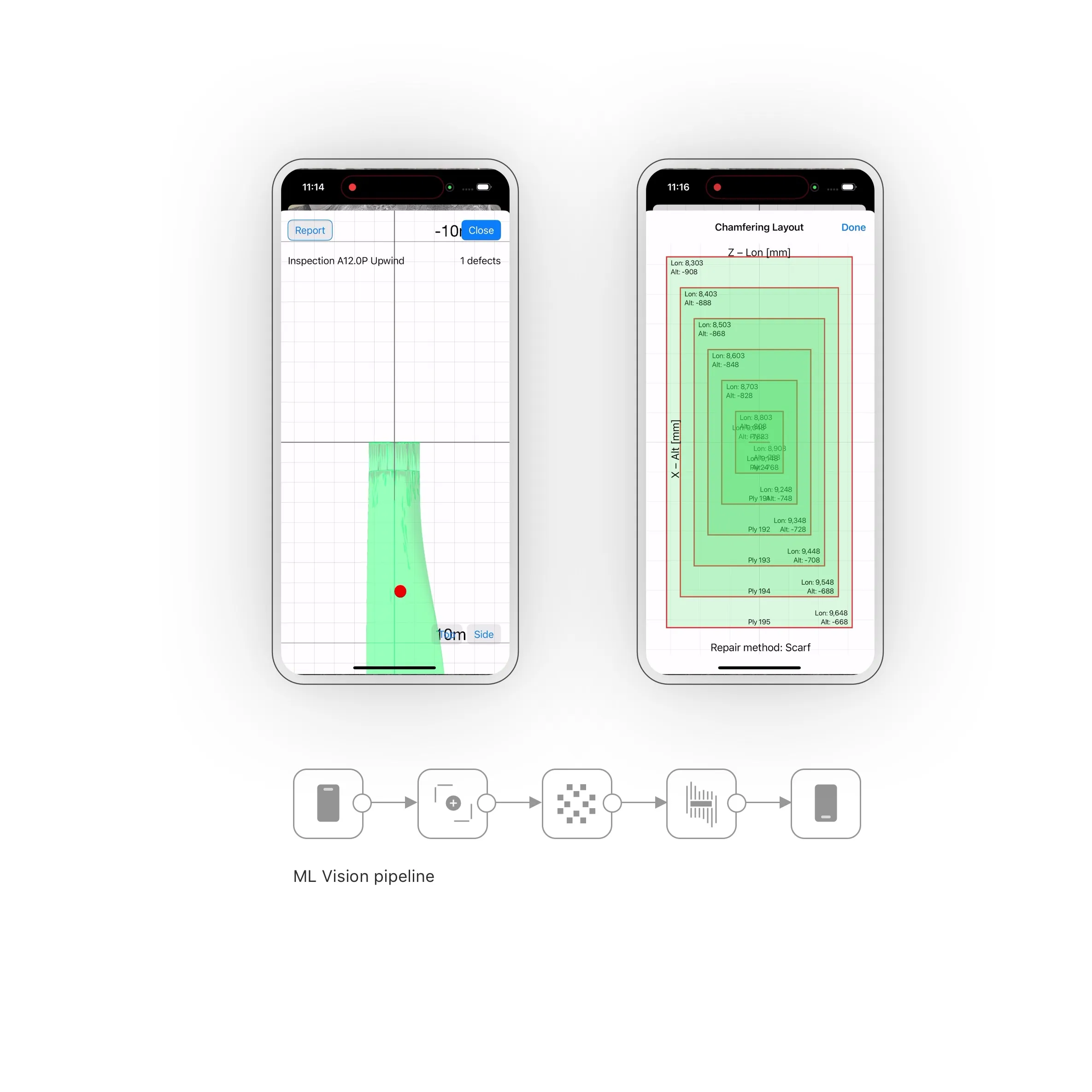
ML intelligence
Purpose-trained models for complex defects
ML vision models cover the full defect spectrum for large industrial surfaces and wind turbine blades. Models are trained on domain-specific data and updated continuously from session evidence.
- Defect classification and severity grading
- Structural anomaly detection
- Paintwork issues and delamination
- Circularity deviation measurement
- Surface condition grading
- Edge case routing to human experts
Model coverage
-
Wind turbine blades
Full blade surface inspection
-
Large composites
Structural and paintwork defects
-
Marine surfaces
Corrosion and coating failures
Related
Product
Spiral Inventor
Mobile, AI-powered visual inspection for high-mix, low-volume assembly lines. Reconfigure the part registry without re-engineering the line.
Custom
Custom AI vision solutions
Need something neither product covers off-the-shelf? We build custom inspection pipelines on the same engines that power Inventor and Roboscope.
Contact
Start a conversation.
Ready to automate visual inspection on your production floor?